|
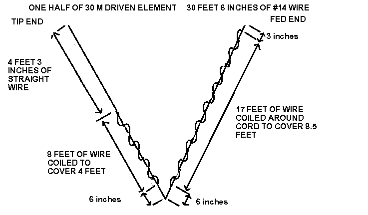
30 Meter HexbeamMy first 30 Meter Hex did not use spreaders at all. I made it by sticking 6 eight-foot poles in the ground 60 degrees apart and at a radius of 13 feet. I added a seventh pole in the center. I strung my wire elements to the poles using nylon cord. The array ended up being about 7 feet off the ground. My driven element was 50 feet long and the reflector was 51 feet.I naturally could not turn the array so it was difficult to check the pattern of the signal coming from the array, but results were amazing. I was able to work dozens of stations with good reports. I then decided to try to make a smaller 30 Meter Hex by using loading. Through experimentation, I found that if I looped the elements around nylon cords I could make the Hex smaller. I ended up looping them so that one foot of wire coiled so that it took just 6 inches of space. That would be two turns (two feet of wire) in one foot of nylon cord. I attached each loop to the cord with a 3" by 1/2" strip of duct tape wound around the point where the wire and loop crossed. Starting from the center hub one side of the director ended up being 31' 11" feet long. That distance was made up as follows: 3 inches straight from hub center to start of first coil, 17 loops each made up of one foot of wire taking up 1/2 foot of space, 6 inches straight to apex where wire element bends back, 6 inches of straight wire to start of next coil, 11 loops each made up of one foot of wire taking 1/2 foot of space, 2' 8" feet of wire straight to the tip.  The other side of the director was identical.
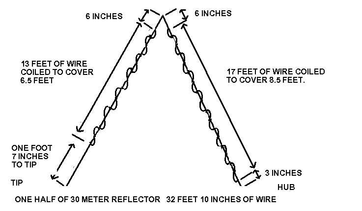
The refector was 32 feet 10 inches long. A leg going out from the hub is the same as it is in the director. 3 inches to the start of the first coil, 17 feet of wire coiled to cover 8.5 ft, and 6 inches to the apex. The leg coming back from there to the tip is 6 inches to the start of the first coil, 13 feet coiled to cover 6.5 feet, and 1 foot 7 inches to the tip. 
The hub is identical to my 17 meter hub. The tip spacing is 14 inches. I maintained tip spacing by attaching the ends of the director and reflector to a 15 inch plastic rod with small holes drilled 1/2 inch in from each end. The wire is #14 stripped "Romex". Here is a close up of how the coils were made. The easiest way to make the coils was to mark the attachment points along both the wire and cord before assembly. At every point where the wire coil was suspended from the nylon cord I used a strip of duct tape (electical tape would be good, too) about 1/2 inch wide and 3 inches long. The distance between the taped attachment points is 6 inches. Use 12 inches of wire between each of these points. I want to make it clear that I make no claims what so ever about this antenna. All I can say is that it displays a low SWR on 30 meters and that I have have numerous great contacts using it. I do not know how to properly model the coils so do not know what to expect. It does not seem to have the front-to-back that I would expect, but then I can not get it high enough to generate a nice pattern. I consider it just a starting point and intend to pursue it. The dimensions I give here work at a height of 25 feet. When the Hex was only at 10 feet, the lengths of each side of both the driven element and the reflector had to be quite a bit longer for resonance in the band. If have seen a difference in each hex that I have built, but not to this degree. I am not sure why. I ended up triming about 8 inches off each of the four tips after I tryed the Hex at 25 feet. The dimensions above are those AFTER this trimming. If you make the hex and test it on a low stand, expect it to resonate high. If you build this hex or any other reduced size 30 meter Hexbeam, please let me know. I want to know what worked for you, and would like to feature your constuction details on this page. I have spent many hours since I built the antenna just described playing with the dimensions. This entailed countless times of lowering my tilt-over tower and adding to, or subracting from, the elements in an attempt to get the antenna to behave a little more like I have become accustomed to a Hexbeam behaving. When I model a 30 meter full-size Hexbeam at 25 feet I do not see anything exciting in the results. Maximum gain is at a very high take off angle of 60 degrees. There it is 6.26 dBi. At 50 degrees it is 6.06. At 40 it is 5.35 and at 30 it is 3.93. The greatest Front-to-back I see is maybe 9 dBi. Obviously 25 feet is not high enough on 30 meters to allow a Hexbeam to show its stuff. With the dimensions I have finally worked out the helically loaded Hex seems to meet or exceed these modeled specs of a full-size Hex, however. After playing with the original version, I decided that I probably did not have enough differential in size between the driven element and the reflector. I also wanted to bring the antenna up in frequency so that the 2:1 swr point at the bottom of the curve was close to the bottom of the band, since all Hexbeams show their greatest front-to-back at that end of the acceptable swr curve. My origianl full-size 30 meter Hex had a reflector 2 percent longer than the driven element. The first loaded version had a differential of close to 3 percent when you looked at total length of wire, but a lot of that differential was lost in the coils. In the latest version below, the driven element and the reflector are 6 percent different when the wire is stretched out. At some point I would like to know what the effective difference is after they both are coiled. I do not know at this point. Anyone know how to figure it? 

I am sure this is not the ultimate solution. I have spent a lot of time on it and it is the best I can do at present. Keep tuned! Let me know if you try building a 30 meter loaded Hex. I am anxious to hear your solution.
I got some of the ideas for the format of this page from Dry-Rain. Check them out! |

